
BaseCam (AlexMos) SimpleBGC
This controller is outdated and is no more sold.
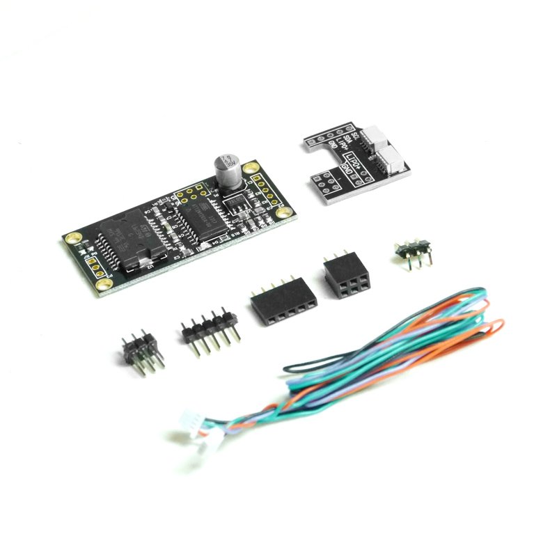
This is the original BaseCam SimpleBGC 8-bit controller board (formerly also called AlexMos). While this board has been superseded by the 32-bit version, this 8-bit version is still available in the marketplace and is actively used and supported. It still produces outstanding results. Without the extension board this controller can be used for building high-quality 2-axis camera stabilizing systems. The controller can also be used for 3-axis control systems with the addition of the extension board. In either case, from a functional perspective the newer 32-bit board is 100% backward compatible with this board, and users of this board can freely upgrade systems from this board to the newer 32-bit board. In addition the management software is backward compatible, so it is possible (or preferred) to use a new version of the GUI (SimpleBGC's management software) with this board- giving an improved experience with this board and also further making upgrade to the 32-bit board as easy as possible.
采用无刷直接驱动电机的摄像机稳定原理
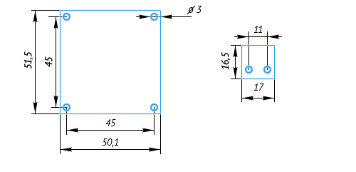
Size of the controller, mm
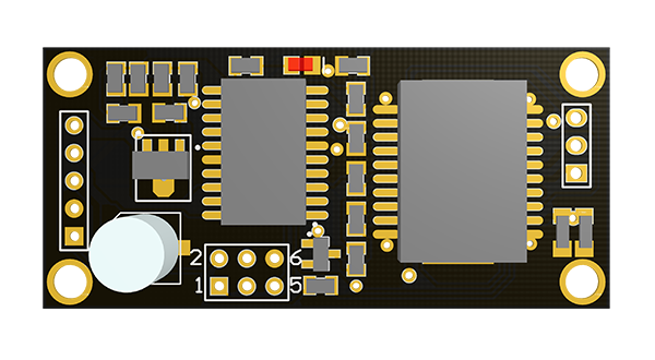
The controller specifications
| Number of stabilization axes | 2 |
| Power supply voltage: | 8..18V (3s-4s LiPo) |
| Maximum DC current to each motor | 2.8A |
| Limiting |
7.1A |
| Output current regulation: | 8 or 32 KHz PWM |
| Sensor connection: | I2C |
| Supported sensors: | MPU6050 |
| PC communication for configuration and upgrade: | |
| Overcurrent protection: | Yes |
| Overheat protection: | Yes |
| Undervoltage protection: | Yes |
| Reverse polarity protection: | Yes |
| Dimensions: | 50mm x 50mm (see drawing) |
| Mounting holes: | M3, 45mm |
Adjustment
The controller board is configured through our multi-platform software product (SimpleBGC GUI). You may run this on a PC, Mac or Linux. A version is also available for Android. The board has upgradable firmware. For any firmware versions, the User Manual and the SimpleBGC GUI software see the downloads section of the website. Follow the link for the 8-bit boards for the correct information. Note that the board has firmware and the GUI software runs externally (on a PC, Mac or Linux etc) but the GUI keeps track of the firmware number and it requires that the GUI revision be at or newer than the the boards firmware. To get all of this information including the firmware, User Manual and GUI software see the download section of our website. While there is a User Manual for the 8-bit version, since you may use the GUI for the 32-bit board with this board (the 8-bit) it may nonetheless be instructive to obtain the newer and more thorough User Manual for the newer 32-bit version. This is especially pertinent if you choose to use the newer version of the GUI with this board. Remember however you can only use firmware for the 8-bit board on the 8-bit board. That you must obtain (if needed) from the download section for the 8-bit board.
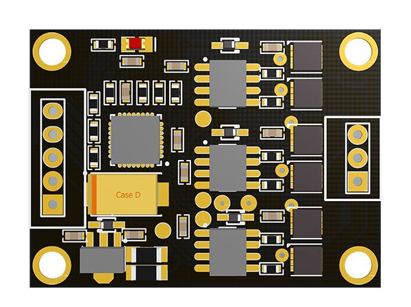
BaseCam SimpleBGC 3rd axis' extension board
Ths board extends the capability of the SimpleBGC 2-axis controller to 3-axis.
Connection
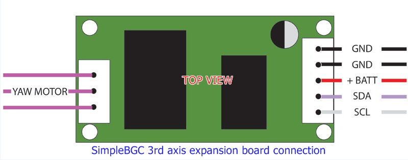
Connection diagram (131Kb 15.05.2013)
To connect the extension board to the SimpleBGC 2-axes controller use 4 wires: SDA (I2C), SCL (I2C), GND (common), +BAT (power).
SDA and SCL are connected parallel to the sensor (note that for the I2C connection, its better to get as short wires as possible).
The 3rd axis board needs of the separate power supply from the battery. When powered by USB, the board doesn't work and is not recognized by the main controller at the start. To activate the extension board, choose it in the Motor Output
On the board there is an LED which displays the mode of operation:
- LED does not light — power is not connected or protection has tripped by a short circuit or current overload (switching off for 1 sec);
- LED lights constantly — power connected but commands are not arriving on the I2C bus;
- LED is blinking constantly — commands are arriving and stabilization is working.
This board works only together with the SimpleBGC 2-axes controller. Stand alone operation is not possible.
When deploying the 3rd axis extension board use the same kind of motors as for the main controller. Do not use regular motors that are for planes or multi-rotors. The internal resistance for power motors is almost zero and it will overload (and likely destroy) the controller board. Use only special motors with windings designed for gimbals with resistance between the phases not less than 5 ohms. The choice of motors (internal resistance) depends on the target voltage. If you use a 2S/3S battery (3S minimum recommended) you can use motors with resistance as low as 5 Ohms but with 10 Ohms being a good choice. For 4S it (the minimum resistance) moves up to about 8 or 10 Ohms. At 5S a good choice is 12 to 15 Ohms (minimum). A maximum of about 30 Ohms is suggested though it may still be possible to extract enough power from the drivers to operate well at higher impedances (depending on the load of the application). Always observe current ratings (5.5 Amps total for all motors).
Where to Buy
Specifications
FET version (discrete components):
| Supply voltage: | 7-21 V |
| Max. current rating: | 5.5 A |
L6234 version:
| Supply voltage: | 7-21 V |
| Max. current rating: | 3 A shortly 1,5 A continuous |
Adjustment
To setup the controller, a special GUI is used. The complete setup procedure is described in the user manual.